
Beading Market
Shop for beadwork made by your fellow beaders at the 3D-Beading.com Beading Market!
Welcome to the Inkscape beading diagram tutorial! If you have any difficulty following this tutorial, please post a comment at the bottom of the page on which you are stuck, and I'll do my best to help!
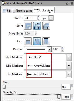
12) While still in the Fill and Stroke box, we will now add arrowheads to our line. Click on the Stroke style tab. Right in this very familiar tab that we have been using, we will find our arrowheads! As you can see in the screenshot, I have selected certain "markers" for my pen line (keep in mind the pen path must be selected to be able to affect it, so if it's not selected, select it by clicking on the pen path with the selection tool). For Start Markers, choose the DotM marker from the list. This places a dot as the starting point of the line (on bead 1). For Mid Markers, choose Arrow1Mend (which stands for Arrow 1 Medium End, where medium refers to the size of the arrowhead, and end refers to the direction it is facing). For End Markers, choose Arrow1Lend, which stands for Arrow 1 Large End. In the same window, choose your desired stroke width (ie, line thickness), and make sure the opacity of the line is 100%, to remove transparency. I have included a second screenshot showing you what your diagram will look like after making these changes. Your arrowheads will all be black regardless of your line's color. We are going to change this next.
13) To change the arrowhead color to match your line (I really don't know why this isn't the default, but anyway...), go to Effects >> Modify Paths >> Color Markers to Match Stroke. You will see a black box pop-up, which is just the command prompt of the program carrying out your request. It will disappear on its own when it's done. Then your arrows will magically all match your line color. I have included a screenshot of the before and after (black arrowheads before, white arrowheads after).
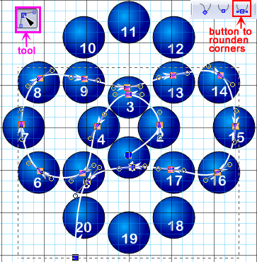
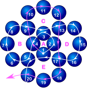
14) So now our arrowheads are the right color, but they don't seem to sit very well on the line, do they? And the line is a bit straight for my liking. We are now going to curve the line, and in the process, the arrowheads will magically adjust to sit right on the line. Select the pen path using the selection tool. With the pen path selected, switch to the transform tool (technically, the "Edit paths by nodes" tool, as it will be called when you hover over the icon). This is the tool immediately below the selection tool in the left toolbar. It is the second tool from the top. It looks like a black triangle pointing at a small blue square, on a curved line consisting of three small blue squares. In my next screenshot, I am showing you what this tool icon looks like in a pink box, but not in its location in the program! When you click this tool, all the "nodes" of your pen path will show. A node is created at every place where you clicked with the pen tool on the beads in the diagram. You will find that there is an arrowhead on every node because that is how the program knows where to add the arrowheads. We will now curve the arrow line. To select all the nodes, drag over the entire pen path using the "edit paths by nodes" tool (current tool). This is important, or else none of the nodes will be selected, even though the pen path is selected. In this tool, we deal with nodes, not the path as a whole. So, with all nodes selected, click on the button at the top of your screen called "make selected nodes symmetric". This button's name won't show unless you scroll over the button. But I am including in my screenshot a picture of this button with a red box around it. It looks like a U-shaped curve, with a blue square at the bottom of the U, and with a small horizontal straight line going through the square under the U. Don't confuse this button with the one immediately to the left of it, which looks like a U with a blue square under it, but without a horizontal line at the bottom going through the blue square. This button also roundens corners, but not as well, and the arrowheads will not be aligned with our line. So use the better button. All you have to do is click once on that button and voila! Your line is so smooth and pretty now, and all the arrowheads are aligned. In my screenshot, you see the diagram at this point, just after clicking the button. All nodes are still selected. You can deselect everything by clicking on the selection tool (black arrow icon in the left toolbar) and clicking away from the diagram. If you are using white arrows, don't worry about the fact that your last arrow isn't showing over the background because in reality your background is transparent, so it will show on the web.
15) Now we want to add the second arrow to depict the other end of the fishing line going through our beads. Do the exact same procedure as with the first arrow (ie, steps 10 to 15). You may draw the second arrow in a new layer, or you can draw both arrows in the same layer, as long as you select the second arrow individually, not with the first arrow. Ie, using the selection tool, select the second arrow by clicking on it, rather than dragging across the whole diagram (which would select both arrows). In short, to make the second arrow, click the pen tool icon, click the first bead, click once per bead after that, press Enter on the keyboard to end the path. Click the Fill and Stroke button, remove the Fill (press X in the Fill tab), add a stroke (press solid fill button in the Stroke paint tab), add arrowhead markers in the Stroke Style tab, adjust them to the stroke color using Effects >> Modify Path >> Color Markers to Match Stroke. Curve the arrow line by selecting the path with the selection tool, clicking the transform tool, highlighting the whole path (this will not select the first pen path because it's not selected by the selection tool) to select all the nodes, and clicking the rounden corners button. That's it! I should mention here, in spite of the dire length of these instructions, that you can always manually tweak the curve if there is any small section of it that you don't quite like. All you have to do is click on the transform tool (the "edit paths by nodes" tool), click once on the area of the path you want to fix, and then once the path is selected, drag with the mouse. The curve will adjust to where you drag.
16) Now we want to move the text out of the way where there is overlap with the arrows. Lock the pen layer, go to the text layer, and unlock it by again pressing the lock icon beside the layers list (bottom left of screen). Click on the selection tool (black arrow, first tool in left toolbar). Click on any text that is covered by an arrow. Drag to move it out of the way. Note that snapping may still be on, and so your text will not go exactly where you want it to. To turn off snapping, go to View >> Snap. This toggles snapping on and off conveniently without having to go into any preferences boxes! With snapping off, go ahead and fix all your numbers by picking them up with the selection tool and dragging them out of the way of the arrows. Note that you will not be able to accidentally select any beads or arrows because we cleverly locked those layers! If you want to, at this point, you can also change the font size on all your numbers if you feel like they are too big or small. Simply use the selection tool to drag over the entire diagram. All the font will be selected. You can now press the T button at the top of the screen and adjust the font size, style, etc. For your changes to take effect, click the Apply button in the pop-up box. You can also adjust the font color using the Fill and Stroke menu if you so desire.
17) The very last thing we should do before saving our diagram (which I forgot to do earlier!) is add the bead circle letters. This is very easy, just click on the type tool (the big A in the left toolbar), click on the diagram to add your text, adjust the style using the T button, and the color using the Fill and Stroke button, and that's it!
18) Now comes the time for saving your file. We will save it in two ways. One is the go to File >> Save As... In this menu, type a name for your file, click on "Browse for other folders", browse for your folder of choice, and click save to save your diagram file! It will be saved as .svg format (which stands for Scalable Vector Graphic), and it will be opened in this program when you double click on that file. This is handy in case you ever want to edit this file again or add to it, as in if you were making a multi-stage diagram. We are also going to save this file as a web formatted image file, so that we can show this diagram on the web. The web formatting will not retain your layers or your shapes as shapes, but as a flattened color image. The web is incapable of displaying .svg vector files, so we must flatten our image into a bitmap format for display on the web. Go to File >> Export Bitmap. The pop-up box will look scary, but it's very simple. All you have to do is click on the "Drawing" button at the top of the box. Then simply click the "Export" button at the bottom of the box! You will find your bitmap image in the same folder as your .svg file, under the same name, except with a .png extention (.png stands for Portable Network Graphic). Your diagram is now complete. Congratulations. Now you can email your .png file to me!! Here is my completed diagram in .png format (not a screenshot this time!)
You will probably be tired of reading after all this, and will want to play with the program itself. So, I am including the actual inkscape diagram file for you to download and open in Inkscape to play with it. Note: Right click to download. If you left-click, the browser will attempt to open the file. You want to save the file to your hard drive so you can then open it in Inkscape.
Right-Mouse Click this link and select "Save Link As" or "Save Target As" to download the Inkscape Diagram File to Open in Inkscape
That's it! Good luck with drawing your beading diagrams! If you want to submit a beading diagram to this website as a pattern, email your file to me at allegra@3d-beading.com
